Original Source: https://ubidots.com/blog/sonoff-rf-bridge-433mhz-hack-using-tasmota/
SONOFF devices allow anyone to turn different spaces such as traditional homes and offices into smart spaces at a low price. They provide a variety of wireless products for controlling and monitoring solutions, which are suitable to build an Internet of Things (IoT) POC without having to spend hundreds of dollars.
However, if you’re interested in building a POC, you’d probably like to have control of the architecture and the services where your data will be hosted and displayed. Based on this, I decided to go further and hack the brain of SONOFF products, creating my own solutions at a low price.

If you want to learn how to hack the SONOFF 433 MHz Bridge to create cool things, you ought to finish this guide. Trust me!
Requirements
- SONOFF 433 MHZ Bridge
- SONOFF PIR Sensor
- SONOFF Door & Windows Alarm
- FTDI USB to TTL Serial Converter Adapter Module
- MiniUSB Cable
Services & Tools:
- NodeMCU-flasher
- CP210x USB to UART Bridge VCP Driver installed. In case you don’t have it, click here to download it.
Step-by-Step
- Architecture Understanding
- RF Bridge Hack
- Setting up RF Bridge
- Node-RED Setup (MQTT)
1. Architecture Understanding
The most important thing we have to do before starting any integration is understanding the architecture behind it.
For this integration we’re going to apply the following architecture:

Basically the RF devices send a flag every time a device changes its status. These flags are received in the SONOFF RF Bridge to then forward the data received to Node-RED over MQTT; this can be done only if the firmware of the bridge is replaced, in this case, we decided to go with Tasmota. Once the data is received in Node-RED, you will be able to manipulate it as you need it, as well to connect it with third party services such as IoT platforms like Ubidots, social media services, voice assistants, or any service that comes to your mind that could allow you to communicate over an API.
2. RF Bridge Hack
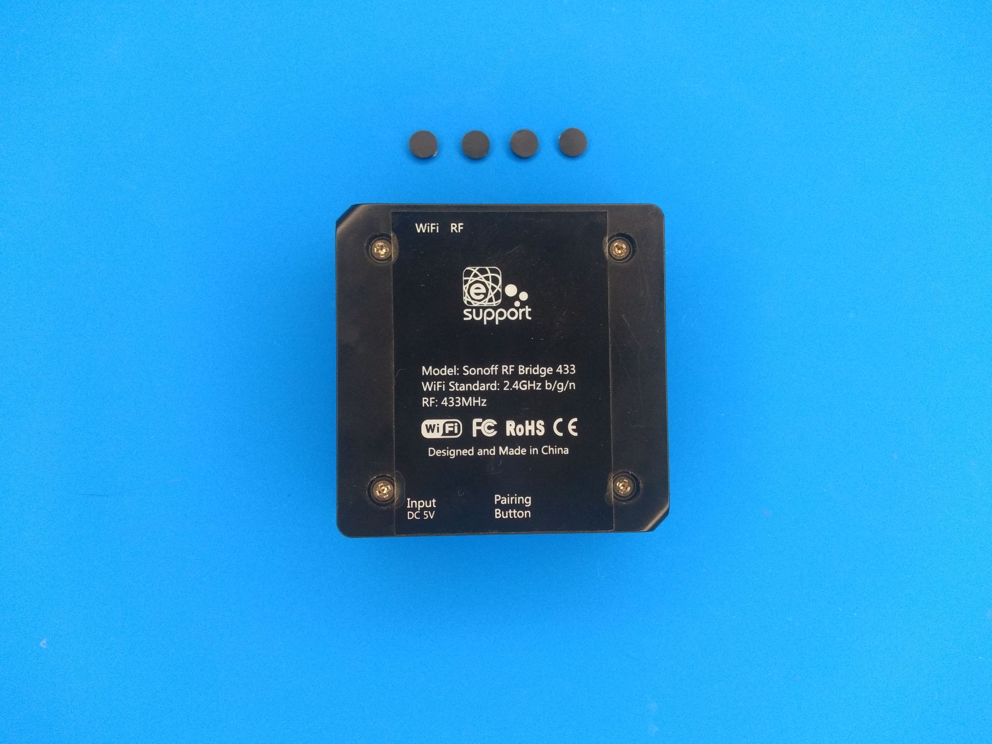
1. Remove the black covers for the 4 screws from the bottom side of the bridge. Then, remove the screws using the proper screwdriver.


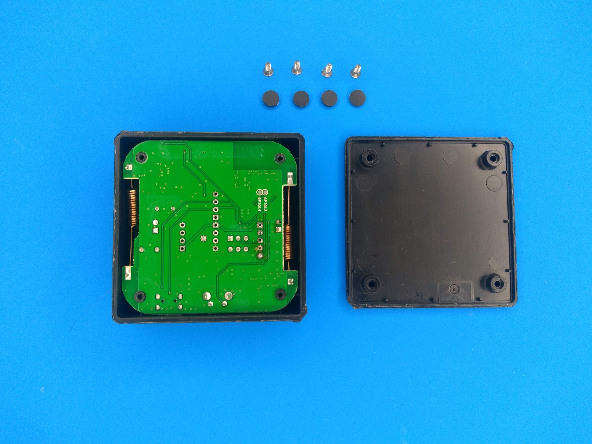
2. Remove the top carefully in order to take out the main PCB. Once you take it apart, you should have the following result:
3. Gently take the board and raise the led’s display. Then, remove the foami located below the display and change the state of the switch to OFF, as shown below:


4. To be able to change the bridge’s SONOFF firmware, you must use a USB serial adapter. To be able to connect the adapter to the bridge, you must solder a few male headers in the pins as seen here:

A second option is not to solder the pins, and use male jumper wires and hold them with your finger during the uploading process.
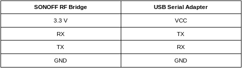
5. Establish the following connection between the module and the bridge:
6. Press the reset button on the bridge, and while pressing the button, connect the USB serial adapter to your computer.
IMPORTANT NOTE: To be able to upload the firmware, you must have the CP210x USB to UART Bridge VCP Driver installed. In case you don’t have it, click here to download it.
7. Based on the OS used, refer to the following tools to upload the Tasmota. Click here to download the bin file.
Windows: nodeMCU-flasher.
1. Start nodeMCU-flasher.
2. In the “Operation” tab, select the COM port assigned to the bridge.
3. In the “Config” tab, select the Tasmota .bin.
4. In the “Advance” tab, make sure the settings match the following configurations:
- Baudrate: 115200
- Flash size: 1Mbyte
- Flash speed: 40 MHz
- SPI Mode: DOUT
As is shown on the image below:
5. To finish, click on “Flash” and get your SONOFF Bridge with Tasmota ready.
Linux/MacOS: esptool
- Refer to the README to run the command required to flash the firmware. Keep in mind the following configurations:
- Baudrate: 115200
- Flash size: 1Mbyte
- Flash speed: 40 MHz
- SPI Mode: DOUT
8. With the firmware successfully uploaded, move the switch to ON and assemble the bridge.
3. Setting up RF Bridge
1. Connect the bridge to any power supply. At this point, the bridge will create an AP (access point). Scan the available networks in your computer and establish the WiFi connection with the one called “sonoff-xxx”.
With the connection established, open your prefered browser and enter the following direction: http://192.168.4.1. At this point you will be redirected to a WiFi setup page.
2. Enter the SSID and password of the desired network you want to establish the connection with and click save.
3. After establishing the connection, use a network scanner app to know the new IP address that has been assigned to the RF bridge. We highly recommend using Fing, which can be easily found in the Google Play Store or Apple’s App Store. Fing is a great tool to easily locate a device’s IP address.
After founding the IP address assigned to the bridge, enter it using the web browser again.
4. As one of the final configuration, you have to set the module to be used, in this case the RF Bridge. To do this, go to “Configuration > Configure Module”. Then, choose “25 Bridge” as module type and click “Save”.

4. Node-RED setup (MQTT)
For testing purposes, you can run Node-RED locally on your computer. If you’re going to deploy a solution, we recommend running Node-RED in a Raspberry Pi connected to the same network of the RF bridge.
1. To set up the MQTT server go to “Configuration > Configure MQTT” on the RF bridge. Then, assign the following configurations:
- Host: Computer’s IP address / Raspberry Pi’s IP address. In my case, the IP address assigned is 10.0.0.23
- Port: 1883
- Client: Leave the default value
- User: Leave the default value
- Password: Leave the default value
- Topic: rfbridge
- Full topic: %topic%/%prefix%/
Having as result:

To finish press the “Save”button.
2. Start Node-RED locally by running the following command in your terminal:
node-redIf don’t have it already installed, click here.
3. Once the Node-RED starts, open a web-browser and write the following IP Address 127.0.0.1 and the port 1880 (i.e http://127.0.0.1:1880) to open the Node-RED web interface.
4. Next, click on the Node-RED menu in the upper right corner, then “Import > Clipboard” and paste the code below:
[{"id":"ff00dda7.75ff7","type":"mqtt in","z":"c32623f3.82eec","name":"","topic":"rfbridge/tele/RESULT","qos":"1","datatype":"auto","broker":"9584b3e4.576fd","x":220,"y":240,"wires":[["e629731e.a86648"]]},{"id":"e629731e.a86648","type":"debug","z":"c32623f3.82eec","name":"","active":true,"tosidebar":true,"console":false,"tostatus":false,"complete":"false","x":500,"y":240,"wires":[]},{"id":"9584b3e4.576fd","type":"mqtt-broker","z":"","name":"Local Broker","broker":"10.0.0.23","port":"1883","clientid":"","usetls":false,"compatmode":true,"keepalive":"60","cleansession":true,"birthTopic":"","birthQos":"0","birthPayload":"","closeTopic":"","closeQos":"0","closePayload":"","willTopic":"","willQos":"0","willPayload":""}]5. In the “Connection” tab of the MQTT node, assign as “Server” the same IP address assigned as host in the RF bridge. In my case, the host assigned was 10.0.0.23:

To save the changes, click “Update”.
6. To start running the Node-RED flow, click “Deploy”.

At this point, the MQTT node will change its status to “Connected”.

Then, select the debug tab to visualize the incoming messages.

5. Summary
In just a couple of minutes, we were able to hack the SONOFF RF Bridge without having to be an expert on hardware.
Now that you’re able to manipulate the data to handle it with any service of your preference, it’s your turn to start extending the capabilities of the solutions that SONOFF products offer to build IoT solutions at a low-cost level.